


P0385 OBD Error Code: Problem & Solutions

OBD Code P0385 - Crankshaft Position Sensor B Circuit Malfunction
The P0385 OBD-II error code can be described as Crankshaft Position Sensor B Circuit Malfunction. This code would indicate that there is a malfunction in the crankshaft position sensor B circuit.
This
trouble code is generic, which would mean that it can apply to all the vehicles
which are equipped with the OBD-II or the vehicles which are made since 1996 up
to the present. The specifications on the definition, the troubleshooting steps
as well as repairs can always vary from one vehicle make to another.
Learn More About OBD Error Code P0385
Want
to learn more about P0385 trouble code? Then you have arrived at the right
place.
The
location of the crankshaft can be measured by the crankshaft position sensor.
This information would then be sent to the powertrain control module. This can
be easily used in some automobiles to help time the spark properly. While in
other vehicles misfires can be detected with its help.
What causes this problem with
the Crankshaft Position Sensor B Circuit Malfunction?
- There
can be damaged reluctor ring that could be missing teeth
- The
sensor output could be open
- The
crankshaft position sensor connector might be defective
- Sensor
output shorted to voltage or ground
- Failure
in the crankshaft sensor
- The
powertrain control module might start failing
- Faults
in the starter motor
- Defaults in the signal plate
- Issue of weak or dead battery
Replace/Repair These Parts To Fix OBD Code P0385
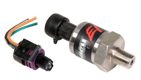
- Crankshaft Position
Sensor - A faulty Crankshaft Position Sensor can be troublesome. You can
always rely on us as we have best auto parts for our customers.
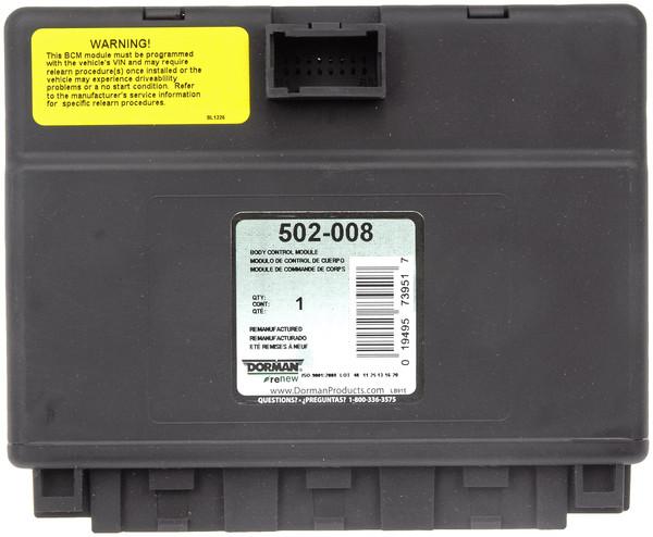
- Powertrain Control
Module - If everything is alright with Crankshaft Position Sensor, then
there is surely some defect in Powertrain Control Module. Get it replaced before
the situation gets worse.
- Battery &
Electrical System Parts - P0385 code can display due to some
issues in the Battery & Electrical System Parts. So, it is very important
to replace the Battery & Electrical System Parts with us at equitable
prices.
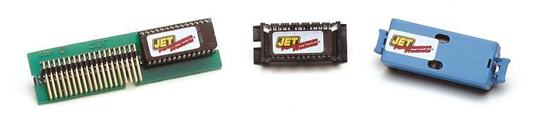
- Engine Control
Module - Do you remember when was the last time you got your car Engine
Control Module checked up? A faulty Engine Control Module can cause a lot of
issues like displaying P0385 code.
- Timing Belt - Are there some faults in your Timing Belt? Don’t waste time and get them replaced or else P0385 code can turn up.
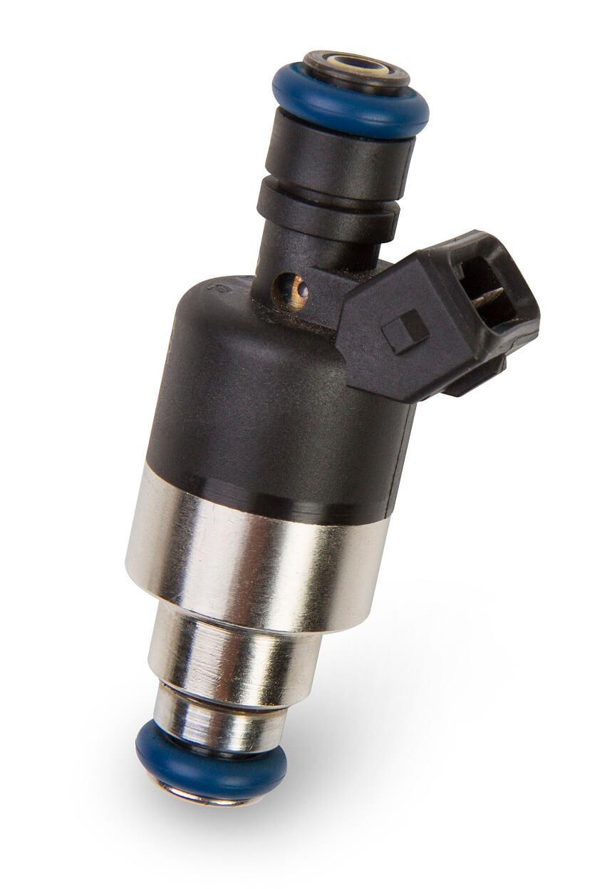
- Fuel Injector - OBD Code P0385 can appear because of faulty Fuel Injector. Visit us to buy top notch fuel injector online.
Symptoms Of OBD Error Code P0385
There
could be countless symptoms which that would accompany with this fault code.
Willing to know some common symptoms of OBD Trouble Code P0385? Your wish is
our demand. Have a look at them below:
Common Symptoms
- The
car may not be able to start properly
- Vehicle cat start running roughly or may misfire
- Malfunction indicator lamp can start illuminating
How To Correct P0385 Crankshaft Position Sensor B Circuit Malfunction
Looking
out for some ways with the help of which you can correct this fault code? Then
you have arrived at the correct place. We are here to help you out, so you must
check out the steps mentioned below as follows:
- Carefully
inspect the crankshaft gear, the position sensor, and sensor connectors to see
if there is any damage if there is no RPM reading
- The
faulty CKP sensor should be replaced
- An
open or a short in the wiring to the crank sensor should be repaired
- Now
once all the repairs have been made, then you must reset the code and test the
vehicle again to see if it solved the problem or not
Don’t get tensed if you are still facing any of these issues as we care for our customers and that’s why we offer a good range of rpm, reluctor ring, timing components and a lot more. We are sure that now all your issues would be resolved.
Easy Diagnosis Of Engine Error OBD Code P0385
It
is essential to diagnose this fault code. Here are some steps which a mechanic
should follow for diagnosing the problem that triggered a P0385 code to be
stored:
- Manufacturers
should utilize the electromagnetic crankshaft position sensor in two different
manners
- Both
designs use either a reluctor ring or teeth which are attached to the
crankshaft to interrupt the field of the stationary electro-magnetic CSP
sensor; creating what is interpreted by the PCM as a square wave form pattern
- These
interruptions provide the PCM with the precise crankshaft position
- In
the first design, the PCM uses the crankshaft position only for misfire
detection and is not critical to spark timing or ignition
- Engine
control systems that use this type of system may allow the engine to start and
run, despite a crankshaft position circuit failure, but engine performance and
fuel economy will likely suffer
- Malfunction
indicator lamp illumination may not occur until multiple failures are
documented in this type of system
- In
the second type of system the PCM uses crankshaft position to calculate spark
timing and ignition control
- A
crankshaft position sensor failure in this system design will normally lead to
a no-start condition, an immediate stored trouble code, and an illuminated
service engine soon lamp (on the first failure). A viable starting point for
obtaining a successful diagnosis of the crankshaft position sensor is by
checking for an engine RPM signal when the engine is cranked or running
- This
is accomplished by using a scanner or observing the vehicle tachometer as the
engine is being cranked (using the starter) or is running, depending upon CPS
system design
- If
no RPM signal is detected, then visually inspect the crankshaft gear,
crankshaft position sensor, and sensor connector for damage and repair as
necessary
- If
no obvious signs of damage are found, then test the CPS system for a reference
voltage signal (typically 5-volts, but check manufacturer’s specifications)
- If
you have access to an oscilloscope, then test the CPS signal wire for the
presence of a square 5-volt waveform pattern for each engine revolution
- If
no pattern is detected then test the resistance of the (disconnected) CSP
sensor and compare the values with manufacturer’s specifications
- If
the CSP sensor checks out, then test the system circuitry for the proper
voltage and resistance
- Repair
open or shorted wiring as necessary
- While
PCM failure is certainly a possibility, it is rare and all other possibilities
should be exhausted prior to condemning the PCM. The camshaft position sensor
and distributor hall-effect sensor are used in a similar manner to the
crankshaft position sensor
- Inputs
between the three sensors help to control ignition timing and fuel delivery. The
camshaft position sensor is an electromagnetic sensor that interacts with a
metal reluctor ring (or gear) on one end or the other of the camshaft
- Engines
that utilize multiple camshafts (dual-overhead cam engines) are equipped with
multiple camshaft position sensors
- As
the reluctor passes by the sensor, a precisely placed hole or gap in the teeth
interrupts the waveform pattern sent by the sensor to the PCM
- This
interruption correlates with an ignition timing reference value that is
programmed into the PCM
- Variations
from the manufacturer’s reference timing value (seen as voltage waveforms) will
cause a code to be stored and possibly a malfunction indicator lamp to be
illuminated. Several specialty tools will be required to diagnose this code successfully
- They
include a scanner, a digital volt/ohmmeter, and possibly an oscilloscope. Begin
with a visual inspection of all wiring and connectors
- Repair
or replace damaged, disconnected, shorted, or corroded wiring, connectors, and
components as necessary
- Always
retest the system after repairs are completed to ensure success. If all system
wiring, connectors, and components (Including fuses) appear to be in normal
working order, connect the scanner (or code reader) to the diagnostic connector
and record all stored codes and freeze frame data
- This
information can be extremely helpful in diagnosing intermittent conditions that
may have contributed to this code being stored
- Continue
by clearing the code and operating the vehicle to see if it returns
- This
will help to determine whether or not the malfunction is intermittent
- After
the codes are cleared, test drive the vehicle to see if the code returns
- If
the code fails to immediately return, you may have an intermittent condition
- Intermittent
conditions can prove to be quite a challenge to diagnose and in extreme cases
may have to be allowed to worsen before a correct diagnosis can be made
- In
the event of an intermittent condition, you may also utilize the oscilloscope
to monitor waveforms created by the distributor, camshaft, and/or crankshaft
sensor/s, while looking for glitches or other inconsistencies. Suspect areas of
system circuitry that are contaminated with oil, antifreeze, or power steering
fluid that has leaked from the engine
- If
wiring with missing or distorted insulation is found, repair or replace it as
necessary. If no obvious system circuitry problems are discovered, perform a
resistance test at the crankshaft, camshaft, and distributor position sensors
and a voltage test on the sensor connector
- Using
your digital volt/ohmmeter test reference voltage at the sensors and compare
your findings with the manufacturer’s specified reference voltage
- If
system reference voltage readings are in line with specified values (or if sensor
resistance values do not coincide), replace the camshaft sensor, distributor
hall-effect sensor, and the crankshaft sensor. Inspect the distributor (where
applicable) for excessive end-play and side-to-side wobble
- If
the distributor is sloppy or worn out, replace it and retest the system for
failures. If system voltage readings do not coincide with manufacturer’s
specified reference figures, check system continuity using your digital
volt/ohmmeter
- Use
caution when checking resistance values in wiring that is connected to the PCM
- For
best results, disconnect the electrical connector from the PCM prior to using
an ohmmeter on the harness side of the circuit
- Remember
that PCM failure is possible but very rare
Common Mistakes When Diagnosing The P0385 Code
- One
of the most common mistakes when you are diagnosing the P0385 trouble code is
that you do not inspect the timing components when the damaged timing belt is
being replaced
- If
there is an illumination in the malfunction indicator light and there is no
noticeable difference in the performance of the vehicle, it could be possible
to believe that it was only the sensor malfunctioning and not something that
was actually wrong with the vehicle
- The technicians should keep this thing in mind that they must look for loose and corroded wiring and connectors, which can give rise to P0385 error code