


P0320 OBD Error Code: Problem & Solutions

OBD Code P0320 - Ignition/Distributor Engine Speed Input Circuit Malfunction
The
Distributor/Crankshaft Position Sensor calculates the precise rotating speed
and crankshaft placement. This gives an important data signal that the
Powertrain Control Module uses (PCM) to manage the Ignition Spark Timing and
Fuel Delivery.
Learn More About OBD Error Code P0320
When the Engine Control Module (ECM) stores the P0320 diagnostic trouble code, it indicates that there is a crash in the ignition/distributor engine speed input circuit.
Let's make a fast backdrop analysis of this system:
- The ignition/distributor engine speed sensor is
motivated to give data to the ECM in consideration to the rotating speed and
placement of the crankshaft.
- Using this data, the ECM is able to control the
ignition spark timing and how the fuel is distributed.
- The ignition/distributor engine speed sensor
may not be working properly, so it may not be able to send a signal to the ECM.
- As an outcome, the ECM will be incapable of controlling the ignition spark timing and fuel distribution that leads to a interference of issues with the car’s performance.
What causes this problem with the Ignition/Distributor Engine Speed Input Circuit Malfunction?
- Rough running engine
- State of Misfire
- Battery on low power
- Rough crankshaft position sensor
- Defective or corroded crankshaft position
sensor wiring and/or connector corroded
- Faulty camshaft position sensor
- Defective or corroded camshaft position sensor
wiring and/or connector
- Rough ignition/distributor engine speed sensor
- Corroded or shorted Ignition/distributor engine
speed sensor wiring or connector
- Rough electrical connection in the
ignition/distributor engine speed sensor circuit
- Damaged ECM
Replace/Repair These Parts To Fix OBD Code P0320
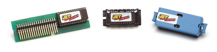
- Powertrain Control
Module - A faulty PCM could get inaccurate to
a degree that your vehicle will fail to start or even stall while running. You
will be seeing emissions shorting out during the running procedure, in turn signalling
that the fuel system control has faltered, so with a PCM that’s not working
correctly, you must have it replaced immediately.
- Battery - When it gets cold, the battery
charge will decline, while the car will need to be boosted to start. To avoid
this situation, a battery should be replaced before its capacity drops to a
critical level. On average, a car battery lasts from 5 to 7 years.
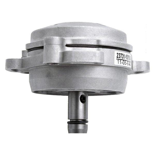
- Distributor
- If
not working properly the distributor can cause serious engine damage. Rough
idling can also be caused by clogged filters. It's hard to tell if a filter is
clogged, so it's best to replace at each tune-up.
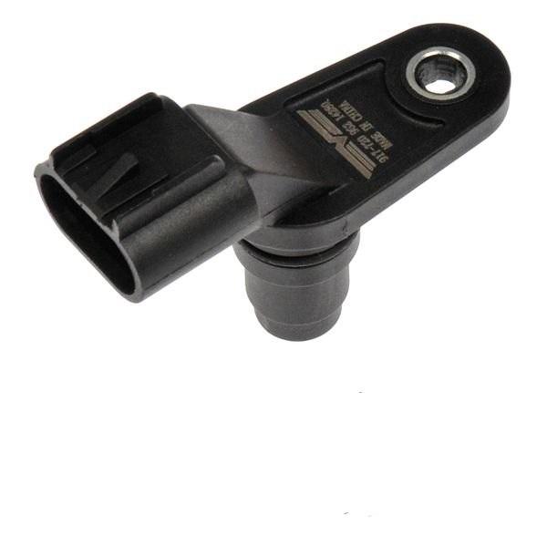
- Crankshaft Position
Sensor - If the crankshaft position sensor or its wiring have any
problems, it can result in the crankshaft signal to be discharged as the engine
is functioning, causing the engine to stall instantly. If your positive that
the crankshaft position sensor has a problem, do get the car inspected by a
professional mechanic.
- Camshaft Position Sensor - As the camshaft position sensor weakens, the signal it transmits to the vehicle's ECM also weakens. Eventually, the signal will weaken so much the signal will switch off, and so will the engine. This can happen while the vehicle is parked, or while you are driving, so the sensor must be replaced.
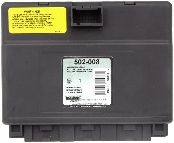
- Engine Control Module - Your car may not start even after making sure that the battery and starter are working explicitly. If your car's problems come down to a failed engine control module, it should be replaced right away to prevent future critical risks to your car.
Symptoms Of OBD Error Code P0320
Our
major objective is to succeed with satisfying our customers, as they mean so
much to us and so we are eager to assist you in diagnosing P0320 code by
sharing some practical symptoms below:
Common Symptoms
- Detect
Engine Light for illumination
- For
most situations, not any irregular symptoms might be seen
- Starting/cranking
hard, but not starting
- Engine delaying or stalling
- Engine fails and won’t start again
How To Correct P0320 Ignition/Distributor Engine Speed Input Circuit Malfunction
If
you want to fix this code defect, then please do follow specific steps. Making
a correction to a issue needs your full-front attention to detail. These are
some helpful tips to guide you to successfully correct the OBD Code P0320:
- Diagnose
and repair any existing low battery voltage settings
- Replace
the crankshaft position sensor
- Replace
whichever crankshaft position sensor wiring or connector that is broken,
shorted, or corroded
- Replace
the camshaft position sensor
- Replace
whichever camshaft position sensor wiring or connector that is broken, shorted
or corroded
- Replace
the ignition/engine distributor engine speed sensor
- Replace
whichever ignition/distributor engine speed sensor wiring or connector that is
broken, shorted, or corroded
- Diagnose
and repair any codes of misfire stored in the ECM
- Replace
or reprogram the ECM, if needed
Regardless, if dealing with any problems, then we provide a stock in a broad stretch of greatest prices for Powertrain Control Module, Battery, Distributor, Crankshaft Position Sensor, Camshaft Position Sensor, Engine Control Module and even more to help you out in repairing your vehicle.
Easy Diagnosis Of Engine Error OBD Code P0320
These
are helpful steps you can follow as a method to diagnose this P0320 fault code:
- Manufacturers
make practical use the electromagnetic crankshaft position sensor in two
divergent ways.
- Each
of these designs use a reluctor ring or teeth that are binded to the
crankshaft, to disrupt the area of the stationary electro-magnetic CSP sensor.
In turn, this produces what the PCM explains is a pattern in the form of square
waves.
- Such
disruptions give to the PCM which is the exact crankshaft placement.
- First
designed approach is when the PCM only uses the crankshaft position checking up
on misfires and does not make a critical review for spark timing or ignition.
- Engine
control systems might enable the engine to start and run when using this kind
of system, in spite a crankshaft position circuit can fail, but the engine
performance and fuel economy is susceptible in suffering.
- A
Malfunction indicator lamp illuminating might not happen until many failed
attempts are recorded with this kind of system.
- Second
designed system is when the PCM uses crankshaft position to measure spark
timing and ignition control.
- A
crankshaft position sensor that is failing within this system design will typically
face up to a no-start setting, where a trouble code instantly gets stored, and
a service engine soon lamp starts
illuminating, when the first failure happens. Many specialty tools will be
needed to successfully diagnose this code.
- These
tools come as a scanner, a digital volt/ohmmeter, maybe even an oscilloscope.
- Start
your diagnosis with a graphic examination of all wiring and connectors.
- Adjust
or Restore any damaged, disconnected, shorted, or corroded wiring, connectors,
and automotive parts as needed.
- After
completing all repairs, constantly survey the system to make sure it is all
successful. If all system wiring, connectors, and automotive parts, even fuses,
show up to be in usually performing sequence, hook up the scanner, or code
reader, to the diagnostic connector and document all codes and freeze frame
data that are stored.
- This
data can be exceedingly useful to diagnosing irregular settings that might have
provided to this exact stored code.
- Persist
with the operation by clearing out the code and running the vehicle to
determine if it comes back.
- This
process will assist in finding out if the malfunction is normal or irregular.
- After
clearing up all of the codes, make sure to test drive the vehicle to determine
of the code comes back.
- If
the code doesn’t succeed in returning instantly, the setting may turn out
irregular.
- Irregular
settings are proven to be very staggering when doing a diagnose and in radical
situations might enable the process to get worse before you can make a proper
diagnosis.
- When
an irregular setting happens, you can make an effective use of the oscilloscope
to survey forms of waves that the distributor, camshaft, and/or crankshaft
sensor(s) produces, as you are searching for errors or discrepancies. A
practical beginning point for making a achievable diagnosis of the crankshaft
position sensor is by detecting for an engine RPM signal when cranking or
running the engine.
- Achieve
this by using a scanner or overlooking the vehicle tachometer while the engine
is being cranked up, by using the starter, or is running, which relies on CPS
system design.
- If
you haven’t detected an RPM signal, then do a graphic examination of the
crankshaft gear, crankshaft position sensor, and sensor connector for corrosion,
damage and adjustments as needed.
- If
you haven’t found any evidence of damage, then examine the CPS system to source
a voltage signal, which is usually 5-volts, but do detect for manufacturer’s
identifications.
- If
you can enter within an oscilloscope, you could examine the CPS signal wire to
spot for an occurance of a square 5-volt pattern in waveform, to make sure
every engine is radically changing.
- If
you haven’t found a pattern, then examine if the disengaged CSP sensor resists
and make a comparison of values when referring to the manufacturer’s
identifications.
- The
CSP sensor may check out, so survey the system circuitry for determining the
correct voltage and resistance.
- Adjust
open or shorted wiring as needed.
- PCM
failure is definitely probably, but it’s uncommon and this should tire any
other likelihood before disapproving the PCM. Being used in an equivalent way
to the crankshaft position sensor is by the camshaft position sensor and
distributor hall-effect sensor.
- Contributions
of data are put in between the three sensors to assist in controlling the
ignition timing and fuel delivery. The camshaft position sensor is an electrode
that communicates with a metal reluctor ring, or gear, on either a single end
or camshaft of the other.
- Engines
that make practical use of several camshafts, especially with dual-overhead cam
engines, are installed with several camshaft position sensors.
- While
the reluctor is flowing past the sensor, a exact situated hole or tooth gap
interferes with the pattern in square waveforms that a sensor to the PCM is
transmitting.
- This
interference has a mutual connection with an ignition timing source value that
set to input within the PCM.
- Discrepancies
by a sourced timing value created by the manufacturer, and visualized in
waveforms of voltage, will result in a code being stored and probably a
malfunction indicator lamp will start illuminating. In case the code comes
back, start with a perceptible examination of the distributor, camshaft and
crankshaft position sensor system wiring, also the electrical connectors.
- Surmise
that system circuitry has locations which are polluted with oil, antifreeze, or
power steering fluid which is dripping out of the engine.
- If
finding wiring that has misplaced or deformed sealed coating, have it adjusted
or restored as needed. If finding no evident issues with the system circuitry,
then conduct a resistance examination at the crankshaft, camshaft, and
distributor position sensors, also a voltage examination on the sensor
connector.
- Make
practical use of the digital volt/ohmmeter test source voltage where the
sensors are at and do a comparison of your discoveries using the clearly
identified source voltage by the manufacturer.
- Ensuring
that system sourced voltage writings match up to the clearly identified values,
otherwise if the sensor resistance values do not occur at the same time,
exchange the camshaft sensor, distributor hall-effect sensor, and the
crankshaft sensor. The system voltage writings may not occur at the same time
as the clearly identified sourced figures by the manufacturer, use your digital
volt/ohmmeter to detect system consistencies.
- Be
safe when detecting values of resistance in wiring attached to the PCM.
- If
wanting better results, disengage the electrical connector out of the PCM,
before using an ohmmeter on where the harness side is on the circuit.
- Take
in mind that PCM falters can possibly happen, but is so uncommon.
Common Mistakes When Diagnosing the P0320 Code
- It
is often a misguided action to out dictate the chance of a faulty cylinder,
fuel injector or PCM. Even further, It is often the case that the diagnosis and
repair of other associated trouble codes, is not accomplished.
- All
other associated trouble codes, a defective cylinder, a defective fuel
injector(s), and/or a defective PCM can all lead to issues with misfires.